
A power adapter for a car car allows you to run everyday devices like handheld computers, televisions, video cameras, and even other power-hungry electrical appliances like refrigerators, hair dryers, toasters, tyre inflators etc.
An auto electrical system is a 12VDC system that runs off the battery and the alternator when the engine is running. This allows you to tap into the system and draw a limited amount of power to run 12VDC devices directly. In most vehicles, at least one automobile auxiliary power outlet is present (see below) and the voltage of the power outlet is usually near 12VDC (13.5V to 15V while the running engine is turning the alternator, in order to charge the vehicle battery while providing electrical power), because it is directly powered without regulation from the vehicle’s electrical system.
To build one cigarette lighter extension cable that included an on/off switch, with a “digital” pushbutton switch to toggle the power flow.
The circuit to allow a momentary pushbutton switch to toggle the power on & off through a cigarette lighter extension cable. Below you can see its complete schematic.
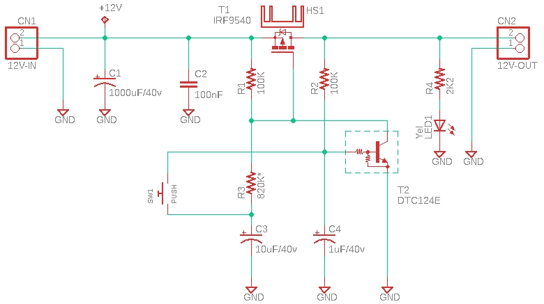
The real switch in this circuit is a solid-state switch which is a P-Channel Power MOSFET – IRF9540 (T1). The IRF9540 available nto-220AB package is certainly a good pick for applications at power dissipation levels to approximately 50W.In this circuit, this Power MOSFET must be used with a heatsink.
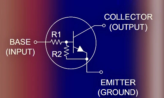
As you can see, there is a second transistor in this circuit (T2) to control the Power MOSFET (T1). The DTC124 transistor is a special BJT often called as BRT (Bias Resistor Transistor). This digital transistor has a couple of integrated 22KΩ base bias resistors, and it’s designed to replace a single device and its external resistor bias network.
During the initial power up, T1 remains in off state and C3 is charged up enough to turn on T2. When the momentary push switch S1 is pressed, the charge on C1 turns on T2, which then turns on T1. Once T1 is on, R2 latches T2. When T1 is turned on, the input 12VDC (CN1) is extended to the output (CN2) instantly. The voltage drop across T1 is only millivolts, so you can see the same (inputted) 12VDC there!
Nevertheless, C3 discharges currently through R3. Therefore, if S1 is pressed again T2 gets turned off long enough to toggle T1. Note that Each Toggle requires to wait few seconds-On Off.
An accidental reverse polarity input can quickly ruin the toggle switch circuit and/or connected appliance(s). So, it is always a good idea to include a reverse polarity voltage input protection circuit with this setup.
Naturally, reverse polarity can damage your delicate electronics when plugged into a dc power source with wrong polarity.
I modified my design by adding a front-end part like this with the help of an additional P-channel Power MOSFET, again the same IRF9540 (T0).
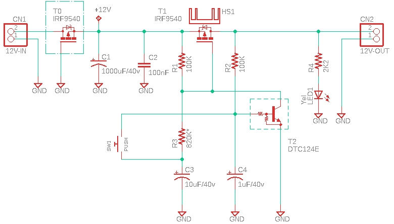
Now when apply a positive voltage on Pin 2 of CN1, the same voltage will also appear on CN2 because the gate of the MOSFET is hooked to GND, and thus the MOSFET will conduct. See, a P-channel MOSFET conducts with negative Vgs. This simple mechanism only allows power to flow when the polarity of the source voltage is correct. Furthermore, this arrangement wastes much less power than a regular silicon power diode would have!